
Completion requirements
Browse the glossary using this index
Special | A | B | C | D | E | F | G | H | I | J | K | L | M | N | O | P | Q | R | S | T | U | V | W | X | Y | Z | ALL
A |
|---|
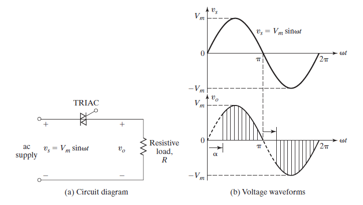
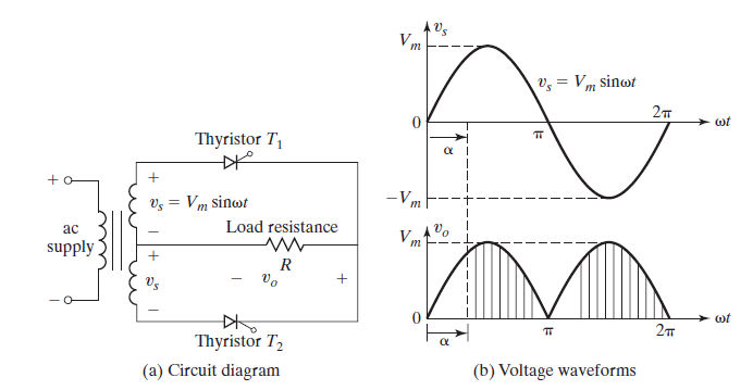
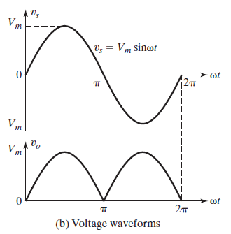
Ac–dc converters.A single-phase converter with two natural commutated thyristors
| |
C |
|---|
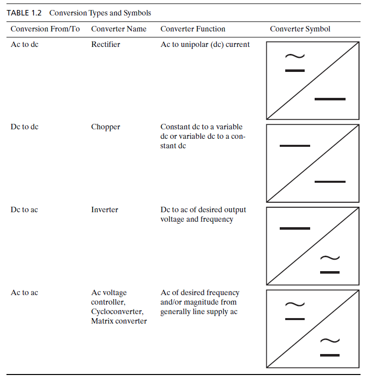
Conversion Type Symbols
| |
D |
|---|
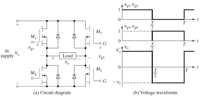
dc–ac converter- is also known as an inverter. A singlephase transistor inverter is shown in the figure. When MOSFETs M1 and M2 are turned on by applying gate voltages, the dc supply voltage Vs appears across the load
| ||
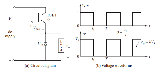
dc–dc converteralso known as a chopper, or switching regulator, and a transistor chopper
When transistor Q1 is turned on by applying a gate voltage VGE, the dc supply is connected to the load and the instantaneous output voltage is Vo = +Vs. When transistor Q1 is turned off by removing the gate voltage VGE, the dc supply is disconnected from the load and the instantaneous output voltage is Vo = 0. The average output voltage becomes Vo(AVG) = t1Vs/T = δ Vs. Therefore, the average output voltage can be varied by controlling the duty cycle. The | ||
diode rectifier- circuit converts ac voltage into a fixed dc voltage
| ||

F |
|---|
free electronsfree electrons enable current flow in the semiconductor | |
S |
|---|
SemiconductorsSemiconductors are materials consisting of elements from group IV of the periodic table and having electrical properties falling somewhere between those of conducting and of insulating materials. Aconducting material is characterized by a large number of conduction-band electrons, which have a very weak bond with the basic structure of the material. | |
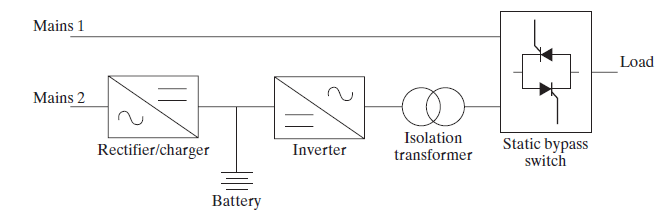
Static SwitchesBecause the power devices can be operated as static switches or contactors, the supply to these switches could be either ac or dc and the switches are known as ac static switches or dc switches. | |